Sunday, 5 February 2017

The CutAway Shader - A free Blender add on for architectural visualisation, model cutaways and more.


After 3 years in the making - I'm excited to announce the alpha release of the CutAway Shader - a free addon for Blender for artists, architects, scientists and engineers.

If you've ever wanted to cut away a cross section of a model, perform an architectural reveal or carry out some tricky special effects then this is the tool for you! 


It works for still images and for animations.

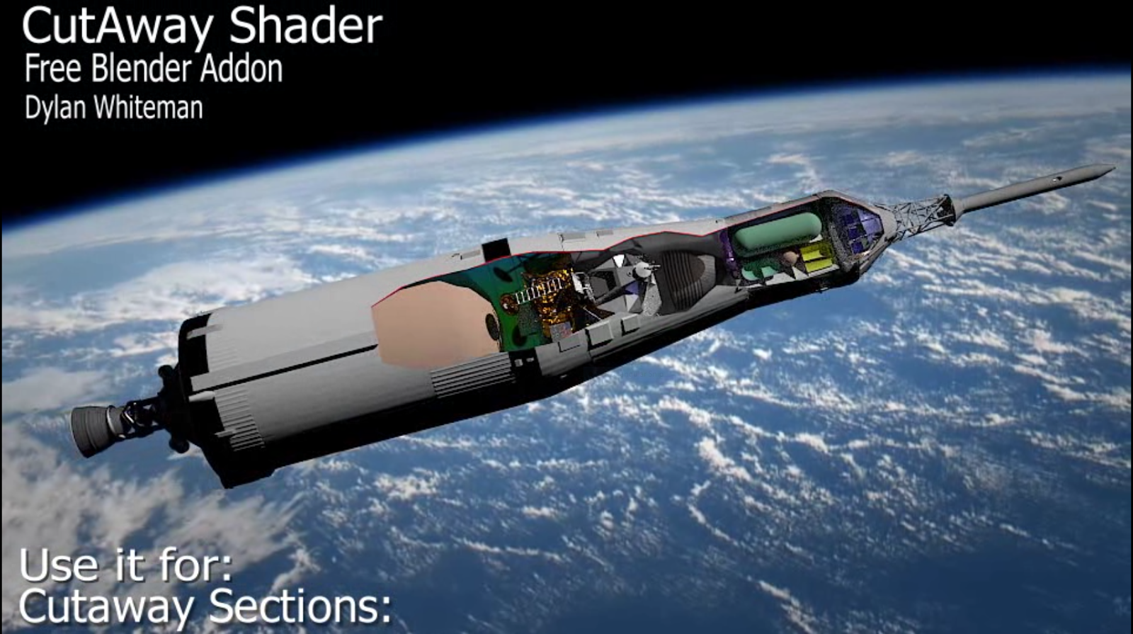
The CutAway Shader can be used for:
  • Model cut aways.
  • Architectural reveals.
  • Scientific and engineering images.
  • Filming through walls (without damaging or re-dressing the set).
  • Special effects (e.g. turning a winter scene into a summer scene).
  • Wire frame to solid model transitions.
  • ... plus much more!


What does it do?

Checkout the CutAway Shader demo reel video on YouTube

Downloading the Addon

  • Download Adddon(.zip)  
    (node_cutaway_shader.zip  v1.2 alpha)
    (This is an alpha release - so remember to save your work!)

Installation

Install the addon in Blender in the usual way. 

or just do the following:
  • File  -> Preferences -> Addons Tab -> Install from file -> node_cutaway_shader.zip
  • File  -> Preferences ->  File Tab -> Check "Auto Run Python Scripts"

Video Tutorials

  1. Installation Instructions and Very Quick Overview Video
    How to download and install the addon - and a very quick intro on how to use the shader.
      
  2. Architectural Reveal with the CutAway Shader: (YouTube link)
    Learn how to reveal the walls and furniture in a house - as seen in T.V design shows and documentaries.

    This tutorial jumps right into it with a practical example - and assumes no knowledge of how to use the shader.
     
  3. CutAway Shader Controls: Overview Tutorial
    All the CutAway Shader controls are covered  - showing what situations they're useful for and how to use them. It is assumed that the shader has already been installed.

    This tutorial is really a compilation of 11 short videos (2 min to 10 min each) covering:
  • A quick overview of the controls.
  • Setting up the CutAway Shader in your scene.
  • Adding cutaway planes.
  • Solidify and Rim Fill options.
  • Cutaway Shape: Rectangular and Circular.
  • Cutaway Shape: From Gray Scale Image.
  • Cutaway Shape: By editing the shape of the cutaway plane mesh.
  • Origin Control Buttons: To help with plane scaling and positioning.
  • Parenting Controls: Easily duplicate parent shaders to selected objects.
  • Auto and Manual Refresh: Viewport speedups.
  • Remove All CutAway Shaders button.

    Each 'mini' tutorial has a heading -- so scroll though the video to get to the desired section, or click on the quick links on the YouTube page.
 ... More tutorials to follow

How does it work? Executive summary

  1. The Cutaway Shader is added as a material node to an existing Cycles material (or materials)
     
  2. Objects in front of the 'green' side of the cutaway plane (that use the assigned materials) will be made fully or partially transparent.
     
  3. A number of helpful controls are available to:
    - Add the Cutaway Shader to multiple materials at once (parenting).
    - Draw a rim at the cutaway cross section.
    - Fadeout the cutaway edge
    - Cutaway arbitrary shapes based on gray scale images, or the shape of the cutaway plane.
      ... plus many more features. (Checkout this tutorial)

Some background info

History: 

After finishing the Open Shader language (OSL) Cycles Lens Flare shader a few years ago, I began experimenting with a few more OSL shader designs. The CutAway shader looked like it would be the quickest to finish (!!!) - so I continued with it.

I noticed with the previous Lens Flare shader release that many people did not know how to add the Blender drivers - these are needed to let the Lens Flare shader know the position of the sun (an 'Empty')  in the scene. A custom 'py-node' in front of the Lens Flare OSL shader could have automated this task. (A Blender py-node is a node that runs Python custom code)

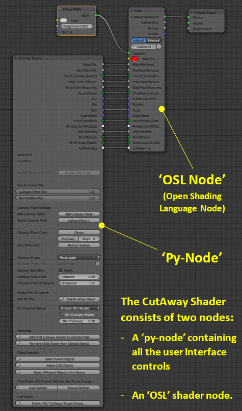
For the CutAway shader release I decided to include a custom py-node to help automate many useful tasks (see figure to the right)

For example, the py-node adds all required drivers automatically. These let the CutAway shader know:

  • The position of the cutaway plane.
     
  • The rotation of the cutaway plane.
The custom py-node also:

  • Colours the cutaway plane in the view port (red on one side and green on the other)
     
  • Provides parenting and duplication functions.
... and a lot of other things too.

This all took quite a lot of time!

Even so, the bulk of the code was finished over two years ago - however, this was followed by the production of 12 demonstration video scenes and several tutorials.

As I am kept very busy during the day project managing this (and like most people have a very busy home life too) this project has taken  approximately 3 years to get to the alpha release stage.


Special Effects Use

Initially I imagined the CutAway shader performing the obvious tasks - Model cross section cutaways, geological cutaways and architectural reveals. But I soon became excited about other uses the shader could be put to.

Special effect Revels: The a shader can easily hide materials on one side of the 'cutaway plane' and (optionally) reveal materials on the other.

This type of effect can be seen in the demonstration video in the following scenes:
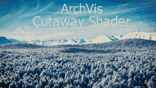
  • Winter Forest -> Summer Forrest scene.
  • Ivy growing on statue scene. 
  • Magic stairway reveal scene.
  • Island forest -> Island city scene.
  • Filming through set walls (see full video)
     
These 'special effect'  examples can easily be extended to many additional scenarios:

  • Revealing car tire tracks in the snow, or in the desert, or on a road.
  • Casting shadows in laser lights shining on a mist.
  • Animated characters 'morphing' from one costume set to another (super hero style)
  • Cat scan style cutaway sections.
  • Easily Cutting holes to let the light into a scene (without affecting the mesh or U.V wrappings)
  • ... etc

Another interesting use for the CutAway Shader is related to the 3D  pipeline work flow. The shader makes it easy to 'punch' any arbitrary shaped hole through scene elements without affecting the base mesh or U.V mapping. If a client wants to move or add an window to a scene at the last minute - none of the existing mesh or U.V work has to be re-worked. The shader will create the new hole with the desired shape and additional geometry (or existing windows etc) can be moved into place.

If the pipeline involves mesh assets the are frozen (or scene dressings that are locked) then the shader offers a new  method of  hiding (cutting away) assets that are blocking the camera view. This can be achieved without actually moving assets or redressing the scene.

This concept extends to 'filming' through set walls - without affecting a set's internal lighting setup, as the shader can be configured to only cutaway 'camera rays'. (i.e. we can look through 'solid' walls without light leaking into or out of the set!)

Filming through sets can be useful for when the desired framing and depth of field results in a lens size that forces the camera to be placed outside the walls of a small set (e.g. a small bedroom, or small space capsule).

So, the possibilities for the Cutaway Shader are surprisingly large for such a simple concept!

Give it a try!

Let me know what you think in the comments below - or e.mail:  iReboot42 at gmail dot com.

Please note:

  • This is an alpha release - so please save your work first. 
  • There are a few 'non-standard' features related to the parenting controls of the shader, These allow the CutAway Shader node to be automatically replicated among selected objects in the scene. Child copies of the parent node are added to the material nodes of selected objects (i.e this feature will alter material nodes in your scene).

Future Work

There are many features that could be added to the shader - along with some optimisations. I would like to look at micro displacement of shaded points in the drawn 'rim' to improve this effect.

Cheers

Dylan

Thursday, 13 June 2013

LensFlare Tutorial Part 3 of 4: Blender Lens Flare: Automatic Masking 


I have just posted a new tutorial on how to achieve automated masking of the lens flare using Blenders compositor.

Automated masking of lens flares can be very useful for complex scenes -- such as in a forrest - where many randomly placed branches may block a lens flare.


Here is an introduction animation showing the automated masking in action:


Here is the tutorial.

It's a little long - weighing in at just over 60mins -- but it has been put together to allow a non-expert to create a scene using the lens flare shader from scratch. Links in the info section below the video allow advanced users to skip ahead.


Here's the Automated Masking Node Setup

The actual node set up is reasonably simple - as can be seen from the noodle below.
The general idea works as follows:
  1. Solid 3D objects in the scene that should block a lens flare are given a Pass Index.
    The IndexOB render-pass is enabled in the RenderLayer(s) for these objects.
  2. A small emission source (e.g an icosphere) is placed on it's own RenderLayer.
    The emission source is parented to the empty that defines the position of the lens flare bloom.
  3. The emission source output image, from its RenderLayer is Multiplied by the output of an IDMask. The IDMask index is set to match the Pass Index from above.

    a) Flare Blocked: When the  emission source is behind a 'solid' 3D objects (white) mask -- then its bright white image passes through the Multiply node. (i.e. 1 x 1 = 1 = small white dot)

    b) Flare Not Blocked: If he emission source is not behind a white mask -- then it does not appear at the out put of the Multiply node. (i.e. 1 x 0 = 0 = totally black image)
  4. The output of the Multiply node is fed into a Dilate node. This will turn the small white dot from 3a into a fully white image that is the size of the render image.

    a) Flare Blocked: Output = fully white image.
    b) Flare not Blocked: Output = fully black image.

    (In earlier version of this noodle - various blur functions were used to spread the dot 'gating signal' to cover the whole image.
  5. The output of the Dilate node is inverted.

    a) Flare Blocked: Output = fully black image.
    b) Flare not Blocked: Output = fully white image.

    Hence this signal can be fed directly to the Fac input off the ADD color mixer that mixes the output from the lens flare render layer with the output from the general 3D scene render layer.


Automated Lens Flare Masking Node Setup (click to enlarge)

The main reason that the video is so long is that it takes a while to go through the steps (for newer users) that allow all the render layers to be setup and the  drivers to be added to the shaders.

There are many more way's to achieve this automated masking effect I'm sure - so it will be interesting to see what people come up with.

This latest invocation is fair;y simple -- and very fast. It does appear to be very 'binary' however. It mostly seems to block - or not block.

Some of the earlers methods that used blur nodes etc were very good at quickly 'fading out' the lens flare as it passed behind objects (such as tree branches or plane wings).

Some tuning can be made with the masking sensitivity however by changing the emission brightness of the source (as seen in the video).

Draw Backs

The compositing method as described above has a key drawback in that once the lens flare bloom moves off the screen (along with its special masking emission source), the compositor can no longer be used to manage the masking -- as it cannot process off screen images.

There are work around for this - such as adding another special emission light source on the 'Masking' Render layer that can be 'keyed' by hand to get the flare into the desired visible state. The lens flare shader's Intensity input itself may also be 'keyed'  in this case.

The Future

I would like to investigate the use of the OSL 'trace' function to determine if any 3D scene objects are occluding the ray from the camera to the 'light source'. I did try this when porting/developing the shader - but without initial success.  It should be possible though - so hopefilly in the future -- extra compositing nodes and render layers will not be required.

Until then however -- this nifty trick seems to work well.

Also in the future - it would be good to see if a Python add on, or a Pynode, could be used to automate the set up of the lens flare render layers  camera plane creation and parenting. Again -- this should be quite do-able - but will have to wait for some development time  ;-)

Monday, 20 May 2013


Lens-flare Shader for Blender Cycles with real time preview

I have been using Blender for several years and have recently started to learn OSL - Open Shader Language.

As a first project I embarked upon creating a lens-flare shader for Blender. In the process I came across a lens-flare shader, written for the Renderman language by Larry Gritz & Tony Apodaca.

I decided to try and port this to OSL - and to my surprise after a day of tinkering it worked! Along the way I added a few features, such as user definable images for lens-flare elements and have got to a point where the shader can now be released. Details about how to download and use this shader are given below - along with video tutorial links.


Before proceeding, a big thanks to the original authors of the shader, Larry Gritz for his work in making the Open Shader Language available to the world and the Blender developers for creating such a great tool.

In the process of learning OSL (an on-going process) I found the following blogs / links extremely helpful.

Screenshot showing the lens- flare shader node set up, real time 3D preview, and positioning control.
Drivers are used to link the position control Empty to the shaders "LightPosition" input.

Lens-flare Shader Features:

  • Real time 3D viewport preview.
  • Shader output may be connected directly to a Material's "Surface" node connection (easy node setup).
  • Lens-flare light source position co-ordinates may be set by the user.
  • Highly customisable Bloom, Starburst, Rainbow, Disk, RIng,Blot and Hole elements.
  • Number of spots, and the distribution of spot type, may be varied by the user.
  • Optional user definable images for all lens-flare elements (new feature).
  • Full control to mix between synthesised lens-flare and user image based lens flare.
  • Lens flare elements may be drawn in GIMP - Photoshop - Downloaded - or other.
  • Easy color tinting.
  • Simple random color variation user settings.
  • Automatic or user definable aspect ratio setting (e.g. for anamorphic lens-flare).
  • An Extensive selection of Color outputs allow all of the lens flare elements to be further proceed in the node editor if desired.

Shader Set up:

The lens-flare is created by applying the shader to a plane
 parented in front of the camera. An "Empty" is used to define the
position of the flare's light source.
The image above shows the simple shader node set up
for the lens-flare plane material. The "Light Source Empty" position is fed to the
shader using Drivers to set the x,y and z inputs of Value nodes.

Video Tutorials

Two of the planned four tutorial videos have been completed. Follow the links to see an overview of the lens-flare shader features - anda tutorial on how to set up a scene with this shader.
Part's 2 and 4 are yet to be completed - but will go over additional composition features - such as automated masking of the flare as it passes behind objects. (Download the .blend file or look at the node 'noodle' below if you want to try this before the videos are completed).

Download an Example Blend file and LensFlare Shader File (lensflare1v1.osl) 

An example .blend file with an:
  • Example scene
  • lensflare1v1.osl shader 
  • Sample user defined shader textures
  • Masking composite node setup
is available from Blendswap here.

Get a copy of the Shader here!

  • Download a copy of the code below as lensflare1v1.osl - and save into the same directory as your .blend file.
  • Load the file as a script in the materials node editor - and connect directly to the Material output node of a plane parented to the front of a camera. Follow the video tutorials for more information.


/****************************************************************************
* lensflare.sl
*
* Description: This shader, when placed on a piece of geometry
* immediately in front of the camera, simulates lens flare.
* These effects happen in real cameras when the camera points toward
* a bright light source, resulting in interreflections within the
* optical elements of the lens system itself. Real lens flare is
* pretty plain looking and uninteresting; this shader takes some
* liberties but looks pretty good.
*
* Parameters:
* intensity - overall scale of intensity of all lens flare effects
* bloomintensity - overall intensity of the "bloom" effect. Setting
* this to 0 removes the bloom effect altogether.
* bloomradius, bloomfalloff - control the size & shape of the bloom
* bloomstarry, bloomnpoints - control the "starry" appearance of the
* bloom effect (bloomstarry=0 means perfectly round bloom)
* starburstintensity - overall intensity of starburst effect (0=none)
* starburstradius, starburstnpoints, starburstfalloff - control the
* size and shape of the starburst effect
* rainbowintensity - intensity of rainbow effect (0=none)
* rainbowradius, rainbowwidth - size of the rainbow
* nspots - number of "spots" splayed out on the axis joining the
* image center with the light position
* disky, ringy, blotty, bloony - give the relative proportions of
* the 4 different kinds of spots.
* spotintensity - overall intensity scale for the spots
* spotvarycolor - scale the color variation of the spots
* seed - random number seed for many of the computations
*
* WARNING: lens flare is notorious as a sign of cheesy, cheap computer
* graphics. Use this effect with extreme care!
*
***************************************************************************
*
* Author: Larry Gritz & Tony Apodaca, 1999
*
* Contacts: lg@pixar.com
*
* $Revision: 1.1 $ $Date: 2000/08/28 01:30:35 $
*
****************************************************************************/
/*
* Ported from Renderman Shader to OSL: Dylan Whiteman, 2013
*
* Many thanks to the above authors for the amazing OSL.
* Many thanks to the Blender team for an amazing 3D tool.
*
* Apologies to the above authors for any degradation or errors to the original code.
*
* See You-Tube Video Tutorials for use of this shader:
* - LensFlare Tutorial Part 1 of 4: Blender Real TIme Lens Flare Shader Introduction:
* http://youtu.be/Whbq8H6Ltvk
*
* - LensFlare Tutorial: Part 2 of 4: How To Set Up a LensFlare Shader in Blender
* http://youtu.be/mf69t-hKxVk
*
*
* Dylan's Notes:
* - Tested with Blender's 'Cycles' render engine.
* - Added: - Input: Light Position (x, y, z) world co-ordinates. The flare bloom is centred on this position.
* (as OSL does not support "illuminance (P, vector "camera" (0,0,1), PI/2)")
* - Output: Cbloom, CstarBurst, Craonbow and Cring elements for greater user control.
* - Comments for OSL newbies like myself.
*
* - Blender Usage:
* Overview:
* - Create a plane to sit in front of the camera. Parent the plane to the camera.
* - Give the plane a material with this shader's composite output feeding an emission shader.
* Add the emission shader to a transparent shader. The sum feeds the material's Surface input.
* - Feed the 'source' lamp x,y,z position into this shader using 3 Value Input nodes and an RGB combiner node.
* - Use Blender 'Drivers' to get the lamp x,y,z positions into their respective Value input nodes.
* - To save render time, create a Render Layer with just the parented plane present.
* Set this Render Layer's "Samples:" override setting to 1 (only one sample is needed) .
*
* Step by Step:
* 1) Create a plane with (approx.) the same aspect ratio as the render setting. Give the plane a name. e.g lensFlarePlane
* 2) Align the plane with the camera view. The plane should fill the camera view
* 3) Parent the plane to the camera. The plane should now always stay in the same position relative to the camera frame.
* 4) Create a node based material for the lensFlarePlane. Add and connect the following nodes:
* 5) Connect an Emission shader and a Transparent shader to an Add shader.
* 6) Connect the Add shader output to the Surface input of the Material Output node.
* 7) Create a Script node and select this lensflare.osl file as the script.
* 7b) Note: The "Open Shader" check box must be ticked in the Render (camera icon) settings in the Properties panel
* 8) Press the Compile/Update button on the script node. All the input and output nodes should appear.
* If the script does not compile - check step 7b. Check that the patterns.h file is present.
* 9) Connect the Composite output node of the lensFlare01 shader to the Color input of the Emission shader.
* 10) Create a Combine RGB node. Conect the Image output of this node to the LightPos input of the lensFlare01 shader.
* 11) Create an Input Value node. Connect the Value output to the R input of the Combine RGB node.
* 12) Create an Input Value node. Connect the Value output to the G input of the Combine RGB node.
* 13) Create an Input Value node. Connect the Value output to the B input of the Combine RGB node.
* 14) The three Value input nodes just created will be used to pass the x,y,z world position of the lens-flare
* light source to the lens-flare shader. "Drivers" must be added to the 'x,y,z' Value input nodes for the
* lens-flare bloom to be automatically placed in the correct position on the screen.
* ... to be continued
*
*
****************************************************************************/
//#include "patterns.h"
#include "stdosl.h"
#define PI M_PI
/* Helper function: compute the aspect ratio of the frame */
float aspectratio ()
{
point Pcorner0 = transform ("NDC", "screen", point(0,0,0));
point Pcorner1 = transform ("NDC", "screen", point(1,1,0));
float ar = (Pcorner1[0]-Pcorner0[0]) /(Pcorner1[1]-Pcorner0[1]);
return ar;
}
// From patterns.h by Larry Gritz. Copied here so users don't have to save
// header files into the osl search path.
float filteredpulse (float edge0, float edge1, float x, float dx)
{
float x0 = x - dx/2;
float x1 = x0 + dx;
return max (0, (min(x1,edge1)-max(x0,edge0)) / dx);
}
/* The filterwidthp macro is similar to filterwidth, but is for
* point data. */
/* Define metrics for estimating filter widths, if none has already
* been defined. This is crucial for antialiasing.
*/
#ifndef MINFILTWIDTH
# define MINFILTWIDTH 1.0e-6
#endif
float filterwidthp(point p)
{return (float)max (sqrt(area(p)), MINFILTWIDTH);}
/* Helper function: compute the camera's diagonal field of view */
float cameradiagfov ()
{
vector corner = vector (transform("NDC","camera",point(1,1,0)));
float halfangle = acos (dot(normalize(corner), vector(0,0,1)))/2;
return halfangle;
}
// return 0 if u or v is out side the range 0 to 1
// return 1 otherwise.
int uvInbounds(float u, float v)
{
if (u < 0.0) return 0;
if (u > 1.0) return 0;
if (v < 0.0) return 0;
if (v > 1.0) return 0;
else return 1;
}
color rainbow (float x, float dx)
{
#define R color(1,0,0)
#define O color(1,.5,0)
#define Y color(1,1,0)
#define G color(0,1,0)
#define B color(0,0,1)
#define Ii color(.375,0,0.75)
#define V color(0.5,0,0.5)
// color rb = spline ("linear",x, V,V,Ii,B,G,Y,O,R,R);
// Looks like we have to use an array for the moment in OSL
color s[10];
s[0] = V;
s[1] = V;
s[2] = Ii;
s[3] = Ii;
s[4] = B;
s[5] = G;
s[6] = Y;
s[7] = O;
s[8] = R;
s[9] = R;
color rb = spline ("linear",x,s);
float p = filteredpulse (0, 1, x, dx) ;
return rb * p;
}
shader lensflare01 (
vector LightPosition = vector(1.8,6.3,0.6),
color LightColor = color(.52,.52,.52),
float AspectRatio = 0.0,
float intensity = 1.0,
int seed = 143,
string bloomImg= "//textures/flares/bloom.png",
float bloomImageMix = 0.0,
float bloomintensity = 0.1,
float bloomradius = 1.4,
float bloomstarry = 0.5,
float bloomnpoints = 50,
float bloomfalloff = 5.7,
string starBurstImg = "//textures/flares/starBurst.png",
float starBurstImageMix = 0.0,
float starburstintensity = 0.101,
float starburstradius = 0.8,
float starburstnpoints = 50,
float starburstfalloff = 7.1,
string rainbowImg = "//textures/flares/rainbow.png",
float rainBowImageMix = 0.0,
float rainbowintensity = 0.009,
float rainbowradius = 0.55,
float rainbowwidth = 0.7,
string spots_diskImg = "//textures/flares/hexDisk.png",
string spots_ringImg = "//textures/flares/hexRing.png",
string spots_blotImg = "//textures/flares/hexBlot.png",
string spots_blotHoleImg = "//textures/flares/hexHoley.png",
float spotsImageMix = 0.0,
float spotintensity = 0.15,
float spotRadius = 1.0,
float spotvarycolor = 1.5,
int nspots = 50,
int disky = 3,
int ringy = 3,
int blotty = 3,
int holey = 3,
output closure color LensFlare_EmissionShader = 0,
output color CLensFlare_ColorShader = color(0), // All lens flare elements composited
output color CLensFlare_synthOnly = color(0), // The color outputs below allow
output color CLensFlare_imgOnly= color(0), // fine tuning in the material node editor or compositor
output color Cbloom_synth = color(0), // Just the synthesised bloom
output color CstarBurst_synth= color(0), // Just the synthesised starburst
output color Crainbow_synth = color(0), // Just the synthesised rainbow
output color CspotAll_synth = color(0), // Just the synthesised combined rings (disk, ring, blot,holowblot)
output color Cbloom_img = color(0), // Just the image based bloom
output color CstarBurst_img = color(0), // Just the image based starburst
output color Crainbow_img = color(0), // Just the image based rainbow
output color CspotAll_img = color(0), // Just the image based combined rings (disk, ring, blot,holowblot)
// Having access to individual rings allows fine tuning in material node editor or compositor
output color Cspot_disk_only = color(0), // Just the combined disk (synth + image)
output color Cspot_ring_only = color(0), // Just the combined ring (synth + image)
output color Cspot_blot_only = color(0), // Just the combined blot (synth + image)
output color Cspot_hole_only = color(0) // Just the combined holowblot (synth + image)
)
{
// Generate repeatable sequences of 'random' numbers - based on nrand and seed settings.
float nrand = 0;
// Random helper function
float urand () {
nrand += 1;
return cellnoise(nrand, seed);
}
point LightPos = LightPosition;
float aspect = AspectRatio;
// If the user has not defined the aspect ration -- then calculate it based
// on the screen dimensions. NOTE: In Blender this works well when rendering, however
// when the aspect ration calculated for the 3D preview viewport does not match the render window
// calculations UNLESS the 3D preview viewport is sized by the user. Hence -- it can pay to set this by hand.
// Also -- defining the AspectRation manually allows for anamorphic lens flare effects.
if (AspectRatio == 0){
aspect = abs(aspectratio());
}
float lensfov = cameradiagfov();
// illuminance (P, vector "camera" (0,0,1), PI/2); // renderman function.
// dw: In OSL we need get our light source info from the LightPos input connection to the node.
// (GetAttributes does not seem to work as we'd like in Cyles at time of writing).
// Transform the center of the screen (.5,.5,0) in NDC to common (world) coords for later light
// position calcs also in common coords.
point camPos= transform("NDC","common",point(.5,.5,0));
// L is the vector from the cam to the flare light source in common (world) coordinates
// We need it to calculate how bright the flare should be for this cam to light angle.
vector L = LightPos - camPos;
// Ldir is the lens flare axis vector in cam coords.
vector Ldir = normalize(transform("camera", L));
// Attenuate the lens flare effect as the flare source leaves the camera field of view.
float atten = 1 - smoothstep( 1, 2, abs(acos(Ldir[2])) / (lensfov/2) );
float brightness = atten * intensity *(LightColor[0]+LightColor[1]+LightColor[2])/3;
// Position of point being shaded in normalised device coordinates.
// 0,0,0 = top left screen. 1,1,0 = bot right screen in NDC
// Now the screen range is (-1-1,0) top left to (1,1) top right
// (0,0,0) is in centre of the screen - with z axis pointing in camera direction
point Pndc = (transform("common","NDC", P) - vector (.5, .5, 0))*2;
// The actual screen is (most likely) rectangular - so extend the range of the x axis to taking into account the
// aspect ration. This way, 'drawing' that is done in these 'normalise' coordinates (e.g circles) won't be stretched
// when we transform back to common or world space. Let's call this NDCa coords.
Pndc *= vector(aspect, 1, 0);
// dPndc needed for antialiasing.(investigate details wrt cycles implementation later)
float dPndc = filterwidthp(Pndc);
// Calculate the flare source light position in NDCa coords.
// Normalised coords make it easier to use step functions - as the bottom right of the screen
// is always (aspect,1) for all render sizes.
point Plight = (transform("common","NDC", LightPos) - vector (.5, .5, 0))*2;
Plight *= vector(aspect, 1, 0);
// Calculate the distance and angle from the point being shaded to the lens-flare axis.
// The distance and angle from the lens-flare axis determine what shade the pixel will be coloured.
vector Lvec = Plight - Pndc; // lensflare axis vector = lightpos - shadePos (in 'NDC' coords)
float dist = length(Lvec); // dist of the pixel bring shaded to the lens flare axis in 'NDC' coords
float angle = atan2(Lvec[1], Lvec[0]) + PI; // angle of the lens-flare axis
float alpha = 1.0;
/*
* Handle the image of the lamp. There are 3 effects:
* the bloom, a small red ring flare, and the triple starburst.
*/
/* Bloom */
if (bloomintensity > 0) {
float radius = sqrt(brightness)*5*mix(.2, bloomradius, urand());
float bloom = pnoise (bloomnpoints*angle/(2*PI), bloomnpoints);
bloom = mix (0.5, bloom, bloomstarry);
bloom = mix (1, bloom, smoothstep(0, 0.5, dist/radius));
bloom = pow(1-smoothstep(0.0, radius*bloom, dist),bloomfalloff);
Cbloom_synth+= bloom * (bloomintensity) / brightness;
point uv = ((Pndc - Plight)/(2*radius))+point(.5,.5,0);
int useImg = uvInbounds(uv[0],uv[1]);
if (bloomImageMix && useImg){
Cbloom_img = texture(bloomImg, uv[0], 1.0 - uv[1], "alpha", alpha) *
(bloomintensity) / brightness;
CLensFlare_imgOnly += Cbloom_img;
}
}
/* Starburst */
if (starburstintensity > 0) {
float radius = sqrt(brightness)*5*mix(.2, starburstradius, urand());
float star = pnoise (starburstnpoints*angle/(2*PI),starburstnpoints);
star = pow(1-smoothstep(0.0, radius*star, dist), starburstfalloff);
CstarBurst_synth += star * (starburstintensity) / brightness;
point uv = ((Pndc - Plight)/(2*radius))+point(.5,.5,0);
int useImg = uvInbounds(uv[0],uv[1]);
if (starBurstImageMix && useImg){
point uv = ((Pndc - Plight)/(2*radius))+point(.5,.5,0);
CstarBurst_img = texture(starBurstImg, uv[0], 1.0 - uv[1], "alpha", alpha) *
(starburstintensity) / brightness;
CLensFlare_imgOnly += CstarBurst_img;
}
}
/* Rainbow */
if (rainbowintensity > 0) {
Crainbow_synth += brightness*(rainbowintensity / intensity)
* rainbow((dist/rainbowradius-1)/rainbowwidth,
(dPndc/rainbowradius)/rainbowwidth);
point uv = ((Pndc - Plight)/(2*rainbowradius+rainbowwidth))+point(.5,.5,0);
int useImg = uvInbounds(uv[0],uv[1]);
if (rainBowImageMix && useImg){
Crainbow_img = texture(rainbowImg, uv[0], 1.0 - uv[1], "alpha", alpha) *
(rainbowintensity) / brightness;
CLensFlare_imgOnly += Crainbow_img;
}
}
/*
* Now emit the random rings themselves
*/
// We will move up and down the lens flare axis vector- placing rings, spots along the way
vector axis = normalize(Plight);
float i;
// Every time this shader is called (i.e for every pixel) -- the same sequence of random
// numbers (with the resulting random rings etc) will be generated. Set nrand to achieve this
nrand = 20; /* Reset on purpose! */
float synth_intensity = 0;
color img_intensity = color(0);
for (i = 0; i < nspots; i += 1) {
synth_intensity = 0;
img_intensity = color(0);
// (re)generate the 'stats' for this ith spot.
float alongaxis = urand();
point cntr = point (mix(-2, 1, alongaxis) * axis);
// Calculate the position of this ring along the lensflare axis, and the ring's radius.
float axisdist = distance (cntr, Pndc);
float radius = mix (.08, .3,pow(urand(),2)) * spotRadius * distance(cntr,Plight);
// generate UV co-ords that can select the pixel to draw when an image texture is used to draw the spots.
point uv = ((Pndc - cntr)/(2*radius))+point(.5,.5,0);
float alpha = 1.0;
// Check to see if the uv coordinated are outside the image texture plane. (0 = out of bounds)
// This is used to speed up drawing. No need to access texture co-ords for out of bounds uv.
// There is also no need to access texture co-ords if the user does not want to use textures for their spots
int useImg = uvInbounds(uv[0],uv[1]);
if (spotsImageMix ==0) useImg = 0;
// Calculate the color and brightness of this spots pixel
color clr = LightColor;
clr *= 1+ spotvarycolor * color ((cellnoise(i) - 0.5), 0,0);
float bright = 1 - (2 * radius);
bright *= bright;
color spotBaseColor = spotintensity * bright * clr * LightColor;
// Like playing cards in a deck - the user has defined how many disk, ring, blot and hole
// type 'cards' there are in each deck
float alltypes = (disky+ringy+blotty+holey);
// Choose a card type from the deck. It is essential thatt his 'random' choice repeats in the same (exact) sequence
// every time we go through the 'for' loop below.
float type = urand()*alltypes;
// Choose the spot shading method based on the 'card' choice.
if (type < disky) {
// Flat disk
// dw changed from filterstep for OSL compilation. Look at changing back later.
synth_intensity = 1 - smoothstep(radius, axisdist-dPndc/2,axisdist+dPndc/2);
if (useImg) {img_intensity = texture(spots_diskImg, uv[0], 1.0 - uv[1], "alpha", alpha);}
Cspot_disk_only += spotBaseColor * mix(synth_intensity,img_intensity, spotsImageMix);
}
else if (type < (disky+ringy)) {
// Ring
synth_intensity = filteredpulse (radius, radius+0.05*axisdist,axisdist, dPndc); // entirely synthesised disk spot
if (useImg) {img_intensity = texture(spots_ringImg, uv[0], 1.0 - uv[1], "alpha", alpha);} // disk spot from an image
Cspot_ring_only += spotBaseColor * mix(synth_intensity,img_intensity, spotsImageMix); // allow the user (output) access to all ring spots
}
else if (type < (disky+ringy+blotty)) {
// Soft spot
synth_intensity = 1 - smoothstep (0, radius, abs(axisdist));
if (useImg) {img_intensity = texture(spots_blotImg, uv[0], 1.0 - uv[1], "alpha", alpha);}
Cspot_blot_only += spotBaseColor * mix(synth_intensity,img_intensity, spotsImageMix); // allow the user (output) access to all blot spots .. etc
}
else {
// Spot with soft hole in middle
synth_intensity = smoothstep(0, radius, axisdist) - smoothstep(radius, axisdist-dPndc/2, axisdist+dPndc/2);
if (useImg) {img_intensity = texture(spots_blotHoleImg, uv[0], 1.0 - uv[1], "alpha", alpha);}
Cspot_hole_only += spotBaseColor * mix(synth_intensity,img_intensity, spotsImageMix);
}
// Provide the user with all the spot types composited together. Offer the synth output as well as an image based output.
CspotAll_synth += spotBaseColor * synth_intensity;
if (useImg) CspotAll_img += spotBaseColor * img_intensity;
}
// Output the composite of all effects.
CLensFlare_synthOnly = Cbloom_synth + CstarBurst_synth + Crainbow_synth + CspotAll_synth;
CLensFlare_imgOnly += CspotAll_img;
if (CLensFlare_imgOnly != 0 ) {
// only mix in the image flare elements if they exist (speed up)
CLensFlare_ColorShader = mix(Cbloom_synth,Cbloom_img, bloomImageMix) +
mix(CstarBurst_synth,CstarBurst_img, starBurstImageMix) +
mix(Crainbow_synth,Crainbow_img, rainBowImageMix) +
mix(CspotAll_synth,CspotAll_img, spotsImageMix);
}
else
{
// There are no image based flare elemnts -- so the output contains only the synthesised elements
CLensFlare_ColorShader = Cbloom_synth + CstarBurst_synth + Crainbow_synth + CspotAll_synth;
}
float brightAdj = atten* intensity;
CLensFlare_synthOnly *= brightAdj;
CLensFlare_imgOnly *= brightAdj; //CLensFlare_synthOnly
Cspot_disk_only *= brightAdj;
Cspot_ring_only *= brightAdj;
Cspot_blot_only *= brightAdj;
Cspot_hole_only *= brightAdj;
CLensFlare_ColorShader *= brightAdj;
LensFlare_EmissionShader = CLensFlare_ColorShader * emission() + transparent();
}


Automated masking of the flare 

This is the subject of an upcoming video - however if you want the Node
Noodle - either download the .blend file from Blendswap (see above) or copy the node setting below.


Note: An additional lensflare plane with its own shader is needed in front of the camera for this to work)

Finally

I hope to see your example scenes and tutorials on the web  :-)